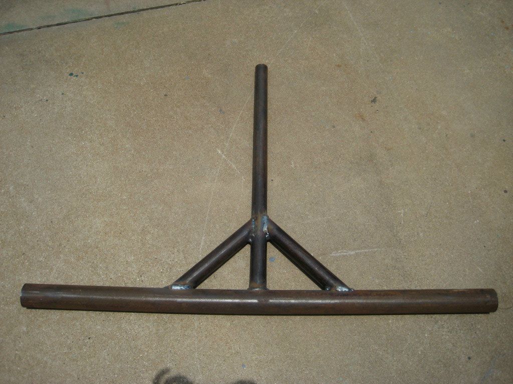
Well a few weeks ago my dad and I decided to build a shooting target for pistols. We were getting tired of shooting the typical paper targets and wanted to take our plinking to the next level! We did some searching online and found some good ideas, but with the $999 price tags, we decided to make our own.
Similar to the deer stand plans that I have posted here before, my dad will make blueprints for every project! That way, we have all of our measurements determined beforehand and not trying to come up with calculation in the garage.
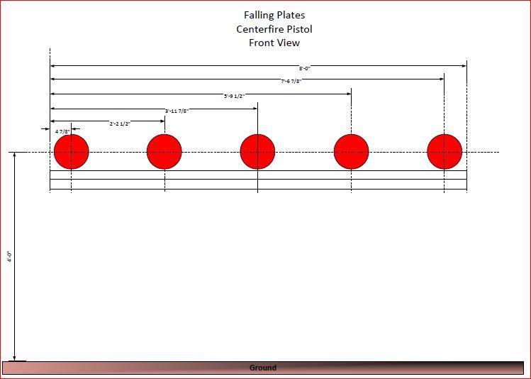
Here are the blueprints:
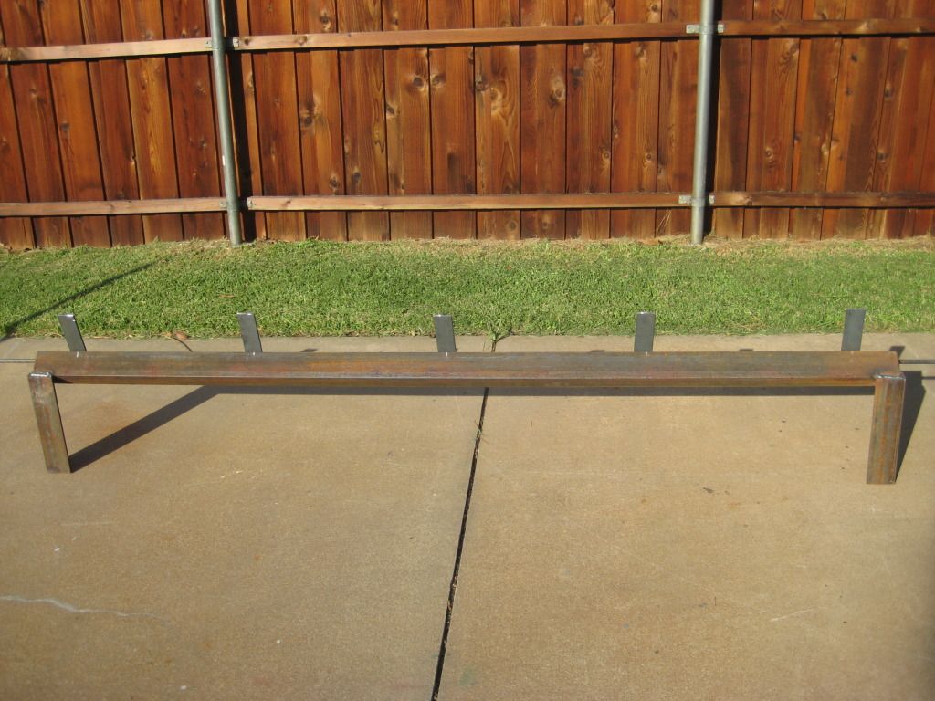
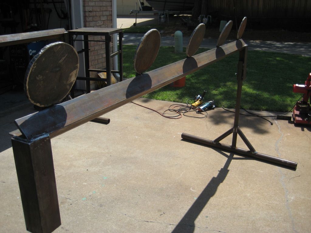
This is how we have all the 8” plates spaced out. Using the program Viso, we were able to measure the middle of his 8’ long angle iron (obviously 4’), then from each end move the targets in a little over 4”. After that, he split the middles between the middle plate and the 1st and 5th plate.
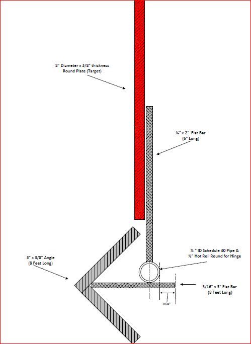
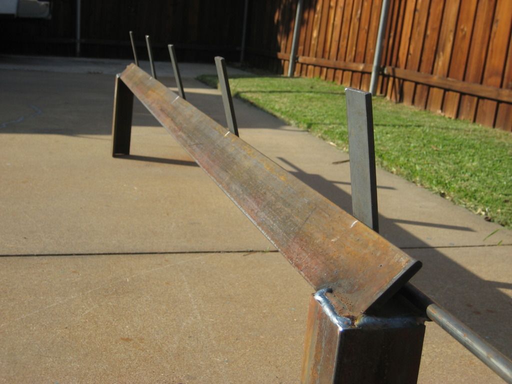
Here is a side view on the 3/8” thick-8” plate welded on to a piece of flat bar. The flat bar has a ½” pipe welded to it. Notice how the main angle iron for this is actually mounted at an angle. From what we read, it is suppose to cut down on ricochets and it also allows you to weld the 8’ long flat bar in the back. The 8’ long flat bar is used to hold and mount all the of plates
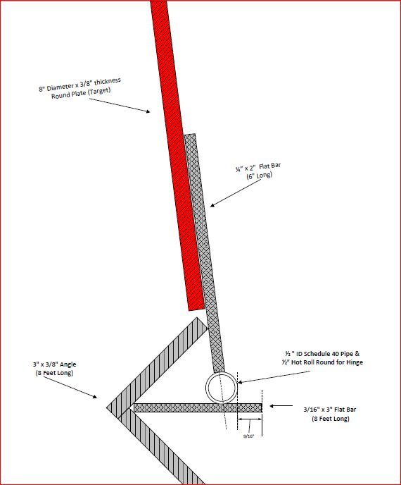
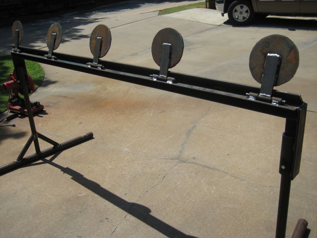
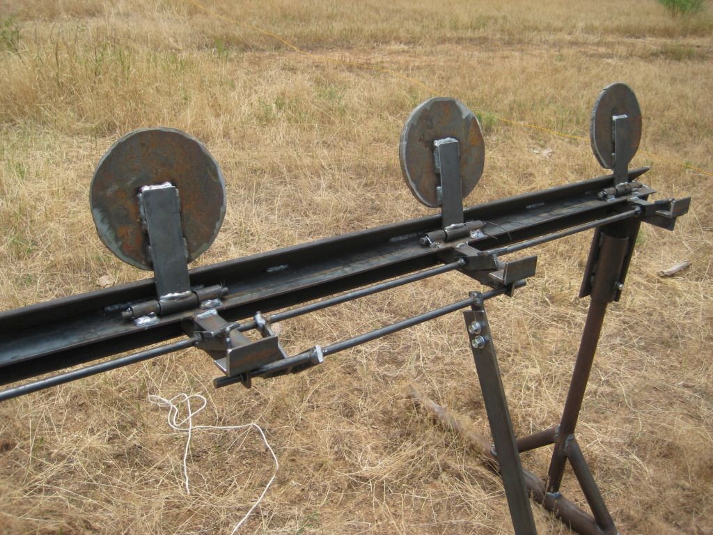
This next picture shows the plates after they are put into place. We knew we wanted to include a pulley/lever mechanism on this, but by doing that we had to make sure the plates would fall past the 90* mark. If we made rest at exactly 90*, then it would have been harder to keep the plates up after we pulled the rope on the lever. We knew that we could adjust this angle once we got to the deer lease. By placing a few rocks on the front part of the legs on the base, the plates will lean back (or closer to the 90* angle). We had to do this once we shot it with a .22 pistol. The .22 didn’t have enough force to knock these plates down at first, but by elevating the front legs, it became a little easier.
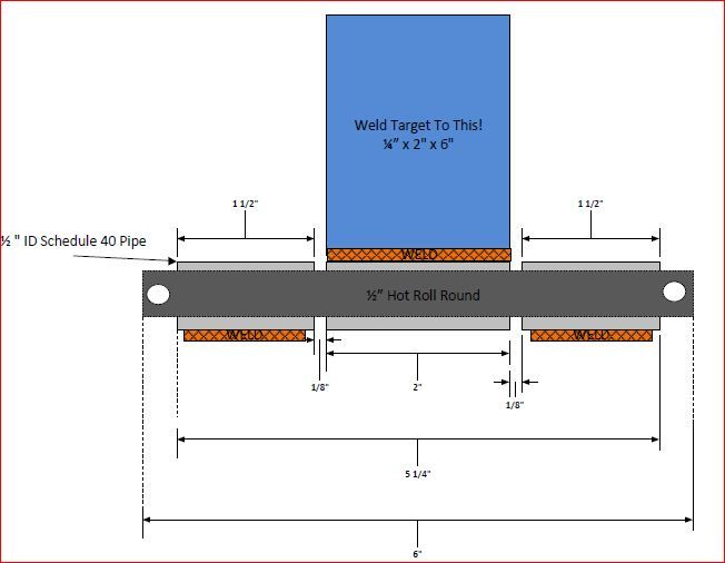
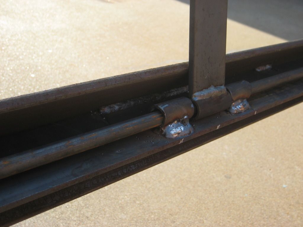
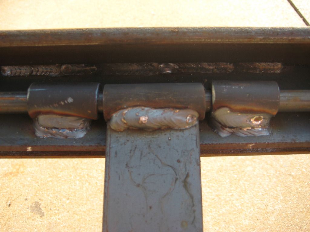
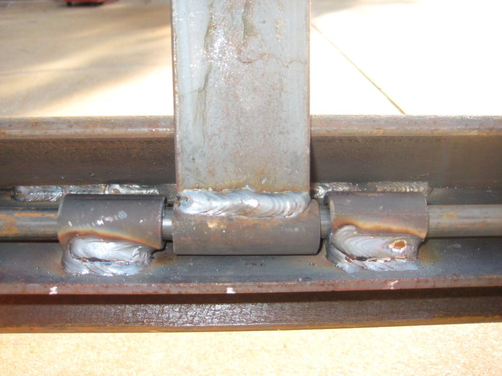
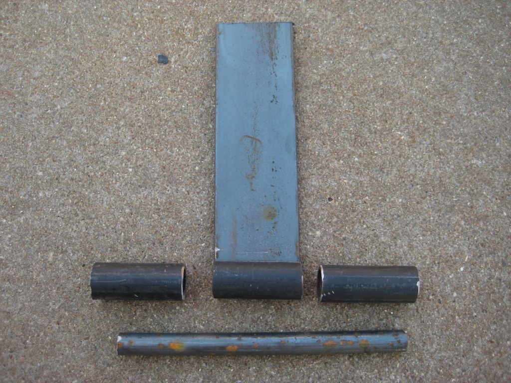
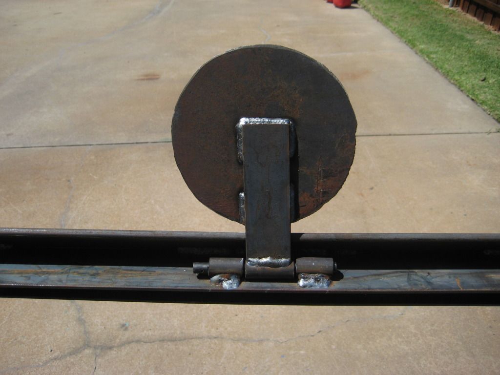
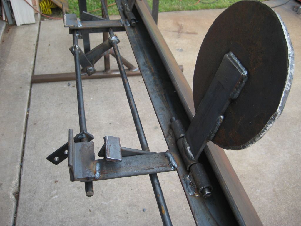
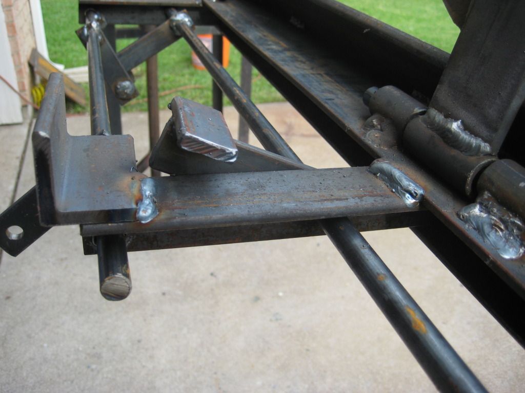
This is how we built our hinges for the plates. The whole idea is that if you wanted to easily remove these plates, you could. Why? Well, if someone accidently broke one, we could take it off and take it home and re-weld it easily. Or, if we wanted to make 10” plate instead of 8” plates, could easily change them out. Or if we wanted to cut out different shapes etc, we could do that too. We just didn’t want to have to worry about bringing this whole target home if we ever had to do repairs to it! It’s freakin’ heavy!
On the hinges, we used 3 pieces of pipe. 2 pieces on the 8’ long flat bar, and one on the small 6” flat bar that is connected to the actual plate. One thing I learned here-when building you own hinge, make sure you use a spacer when welding the 2 pieces of pipe to the flat bar. We just used some thinker wire (bent it in a “U” shape) on our initial welds and removed them and completed the welds) Why? Well, if you don't, your hinge will rub on the 8’ long flat bar. By elevating it some, you get rid of any friction and get a much better hinge.
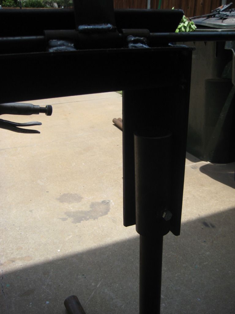
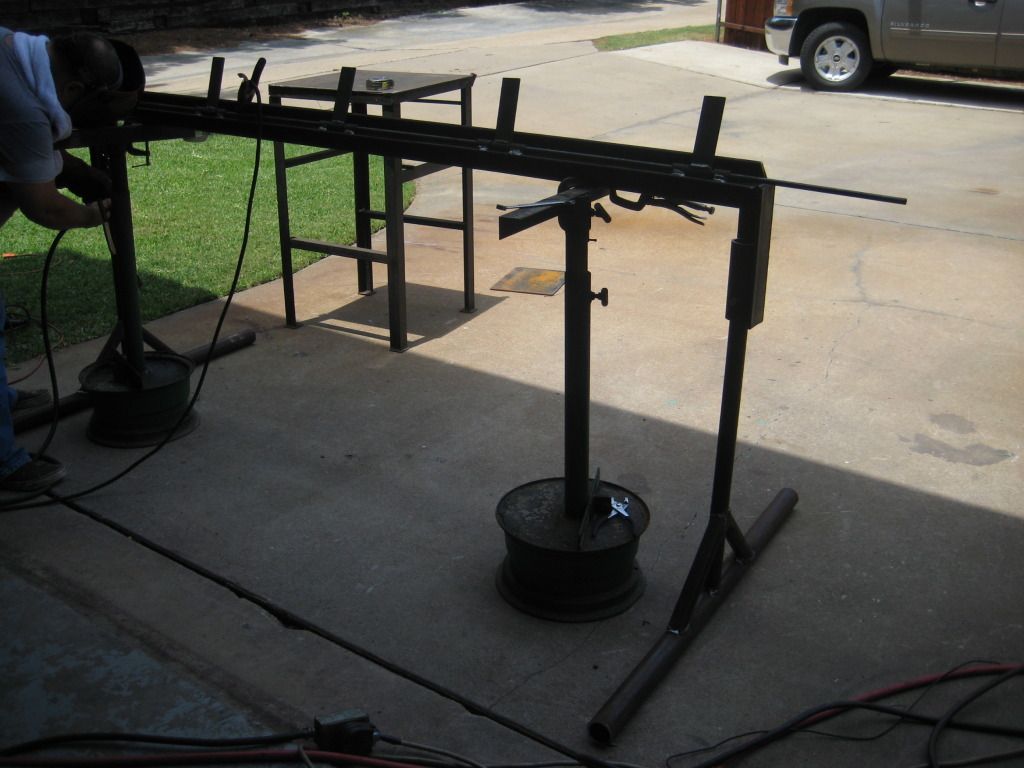
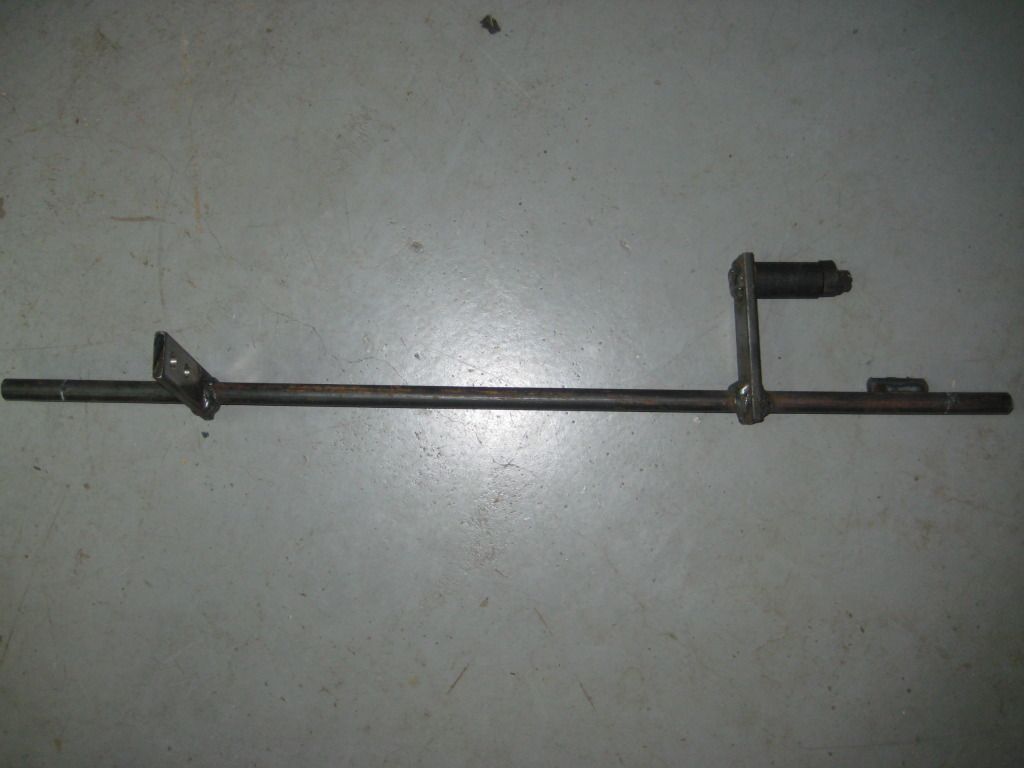
Each plate has a piece of angle iron welded behind it. This is to catch the plate and to keep the hinge from taking all of the weight after the plate is shot. We installed a 8’ piece of round bar that rotates when you pull the lever. On this round bar at each plate, we installed a 4” long small flat bar to act as the lifting tool. This flat bar is welded to the 8’ long round bar so when the round bar turns, so does the 4” flat bar. This rotates forward and pushes the plate up
I have a video at the end showing how we built the lever and pulley system. In one of the shooting video, you can see the lever actually get stuck and not go back into it resting position. We fixed this later with a spring and now it springs back into the correct position!
Ok, now on to the pictures
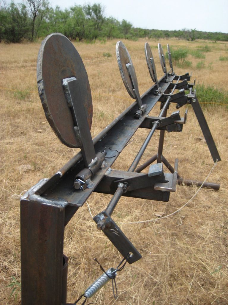
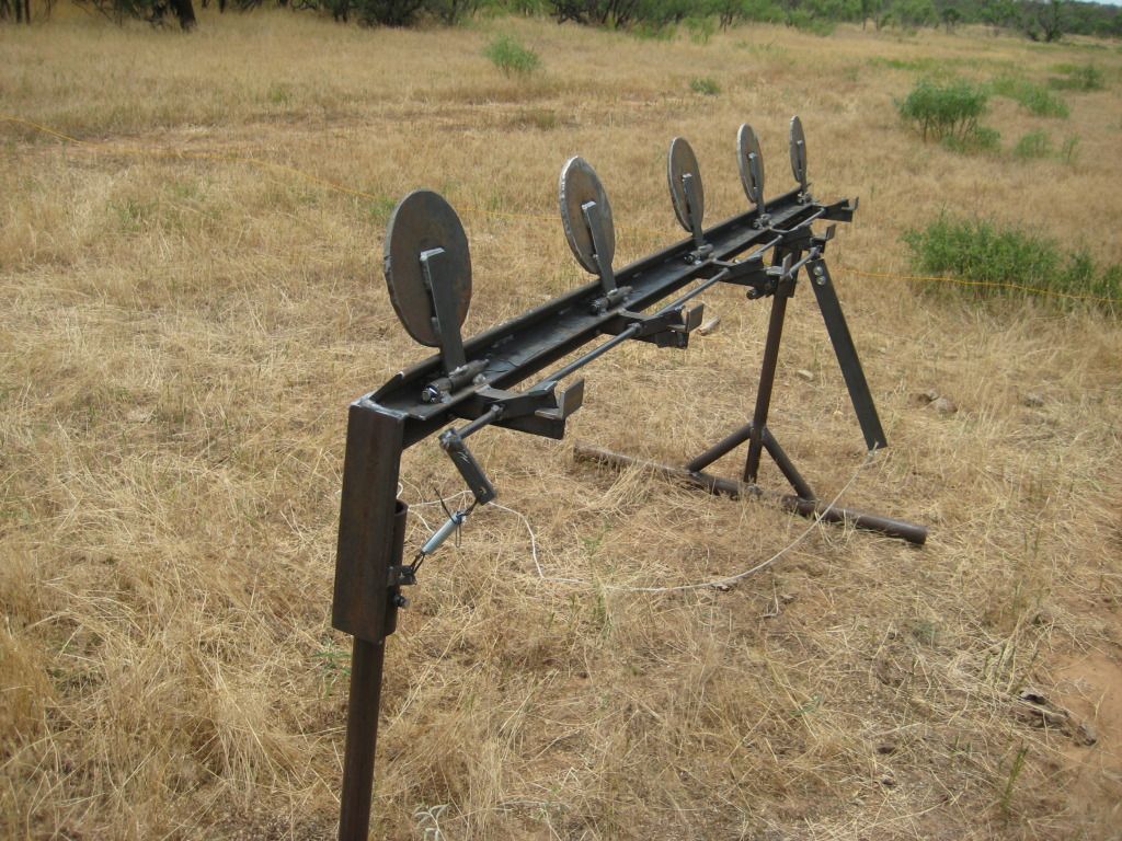
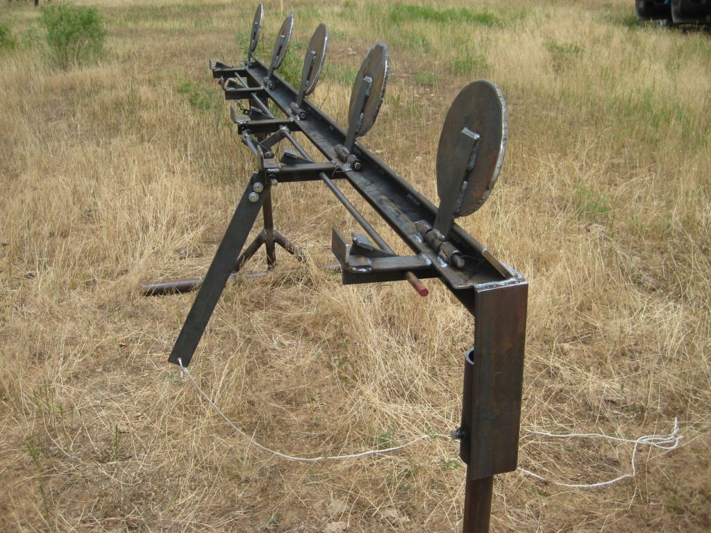
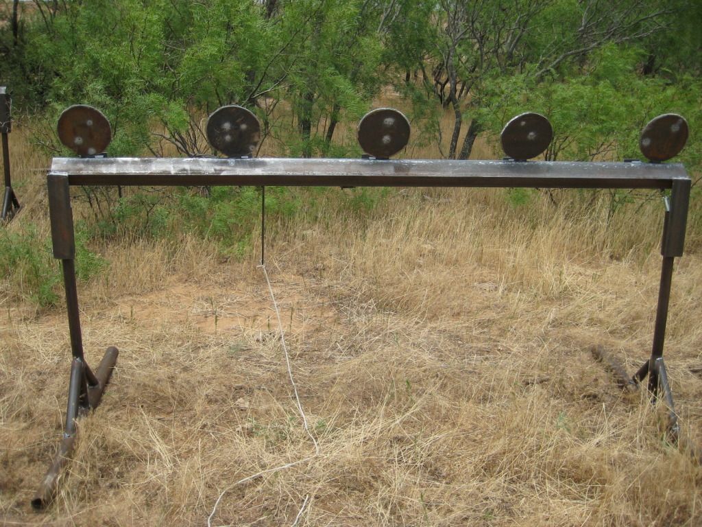
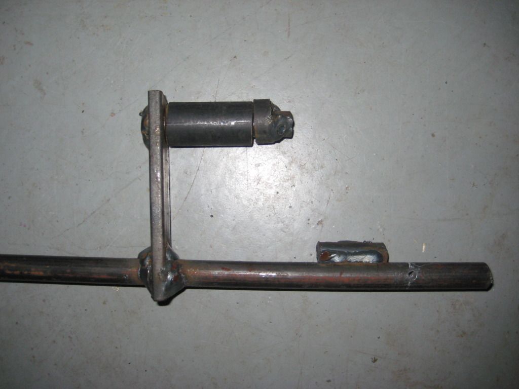
Here is the lever thing
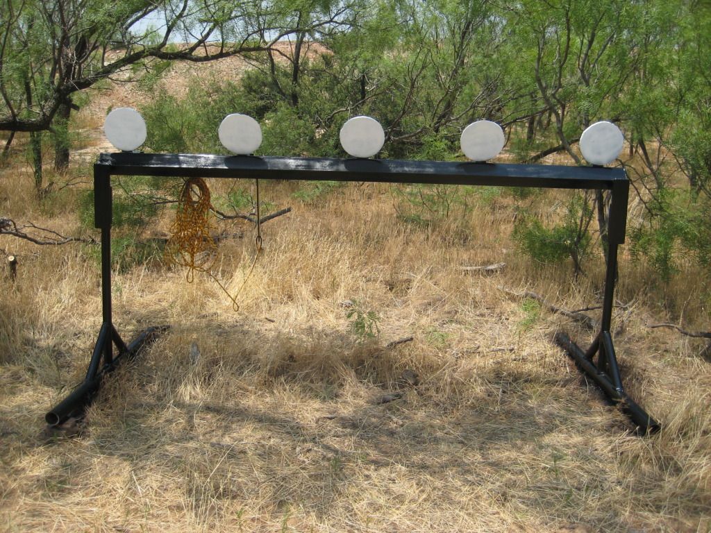
Final Product after paint
Videos
--I'm having trouble loading then now. I’ll try later


